


When designing or constructing canopies, a truss is a common load-bearing element of roof systems. However, many designers are uncertain about which rod cross-sections to select and whether they are used efficiently. This online Truss Calculator for Load and Strength Calculation will help you resolve these issues.
Trusses can be fabricated from either wood or metal. This calculator provides load and strength calculations for both materials. For metal trusses, available cross-sections include square and rectangular hollow sections, angles, channels, and round pipes. For wooden trusses, you can choose from round, square, and rectangular cross-sections.
Steps for using the Truss Calculator:
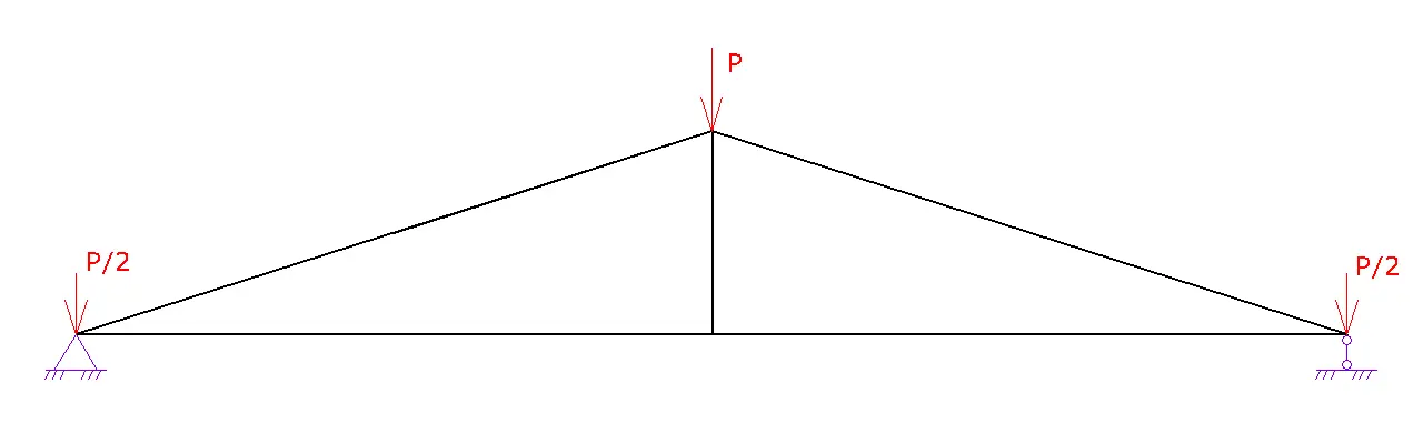
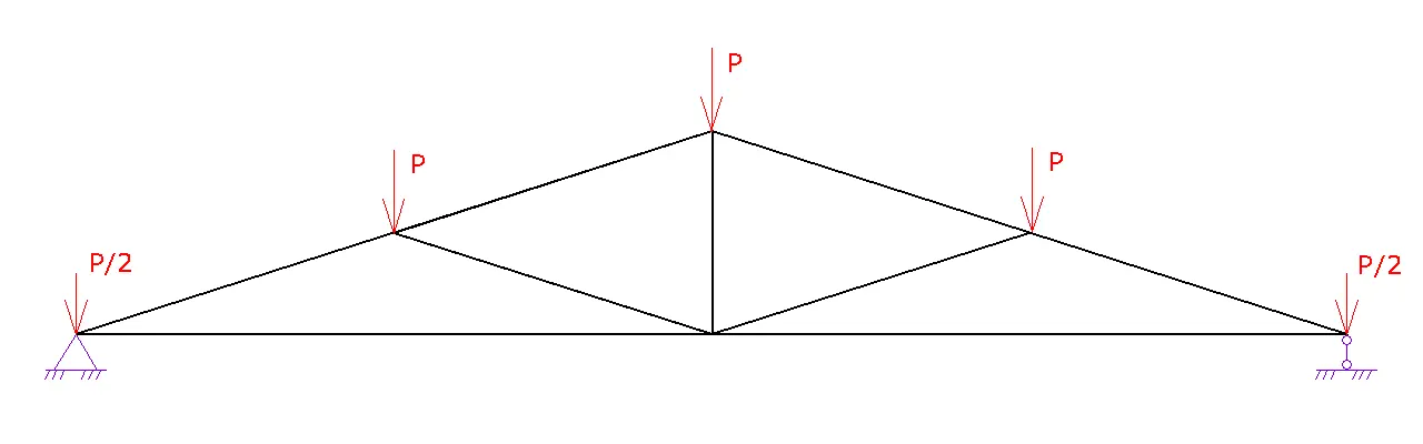
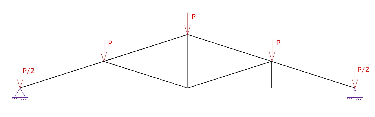
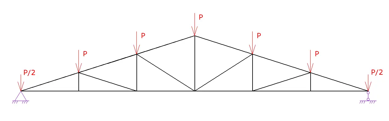
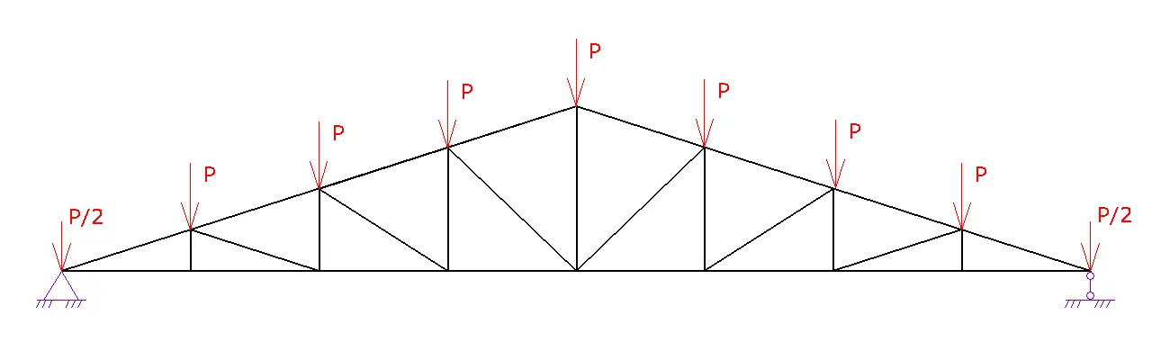
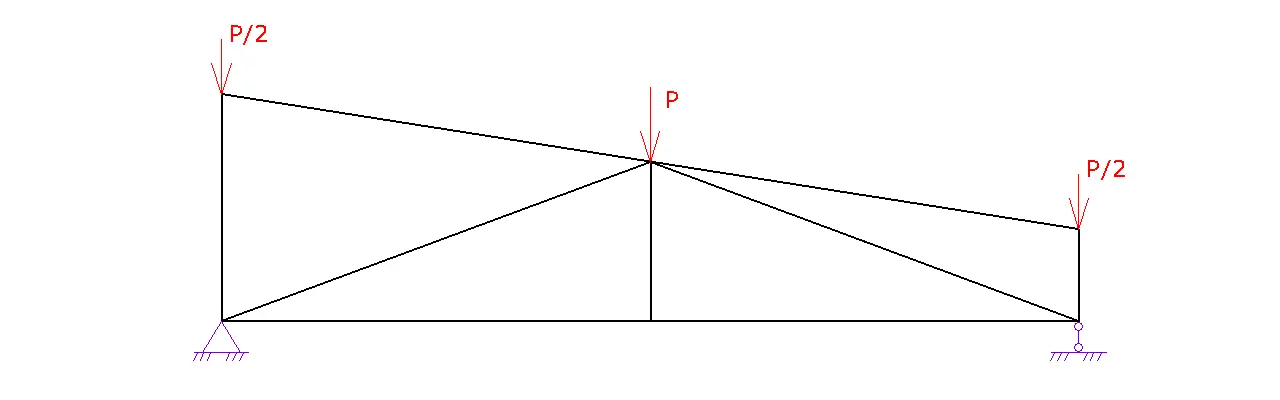
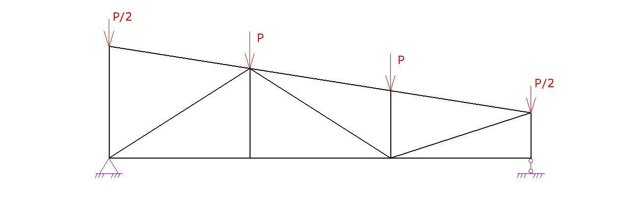
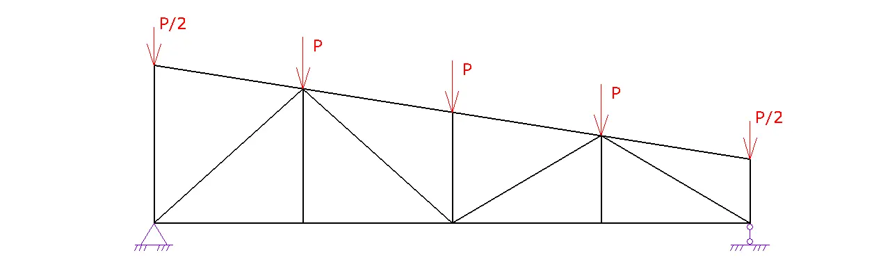
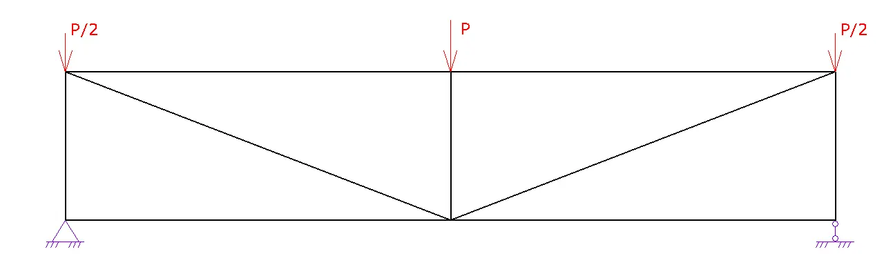
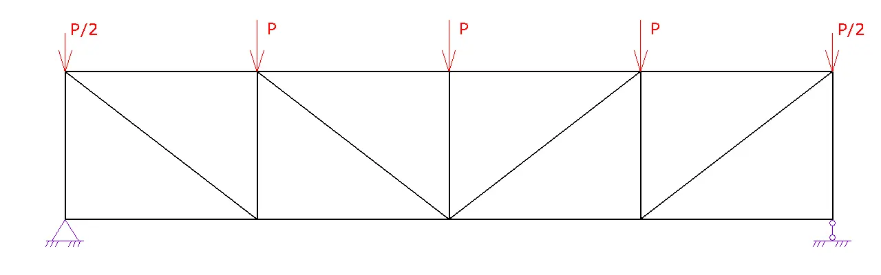
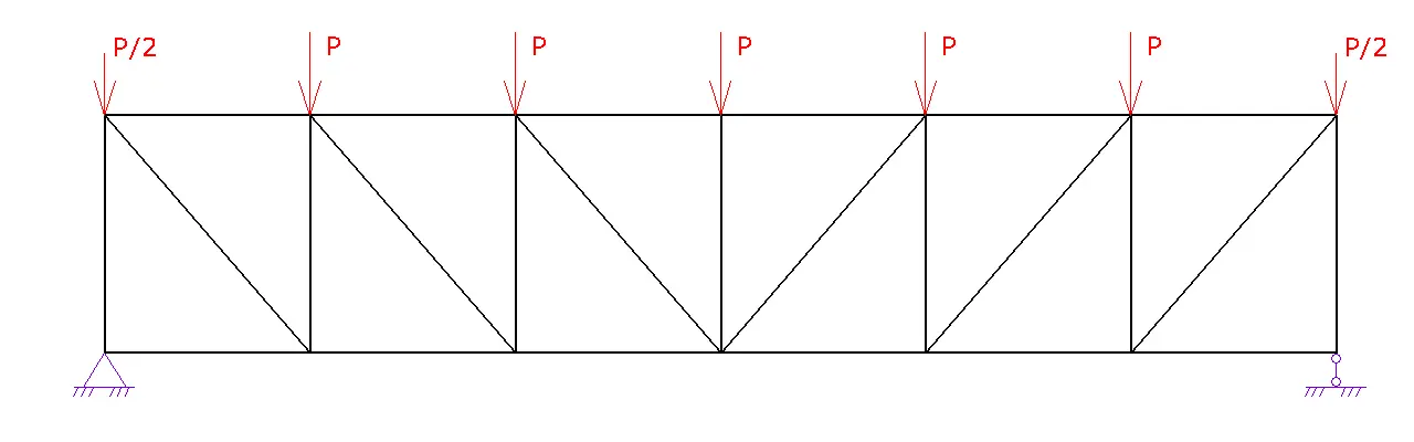
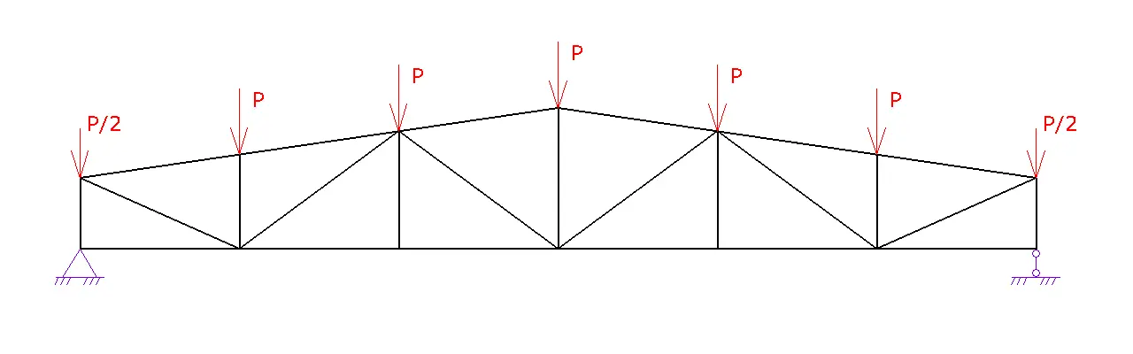
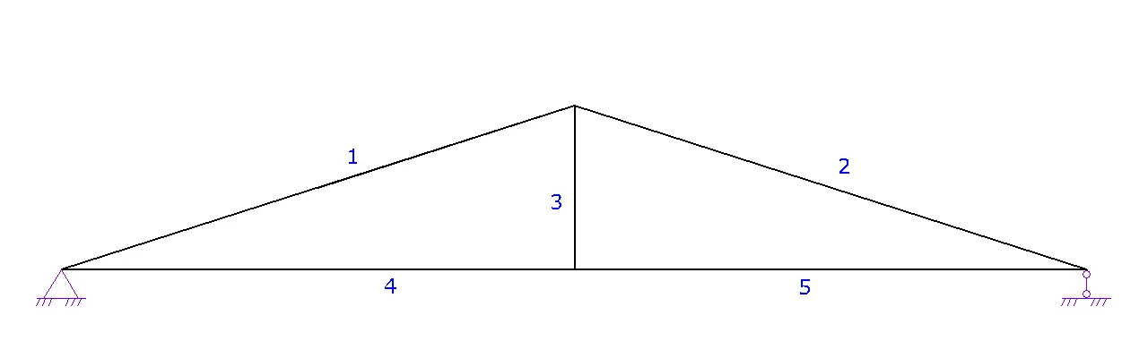
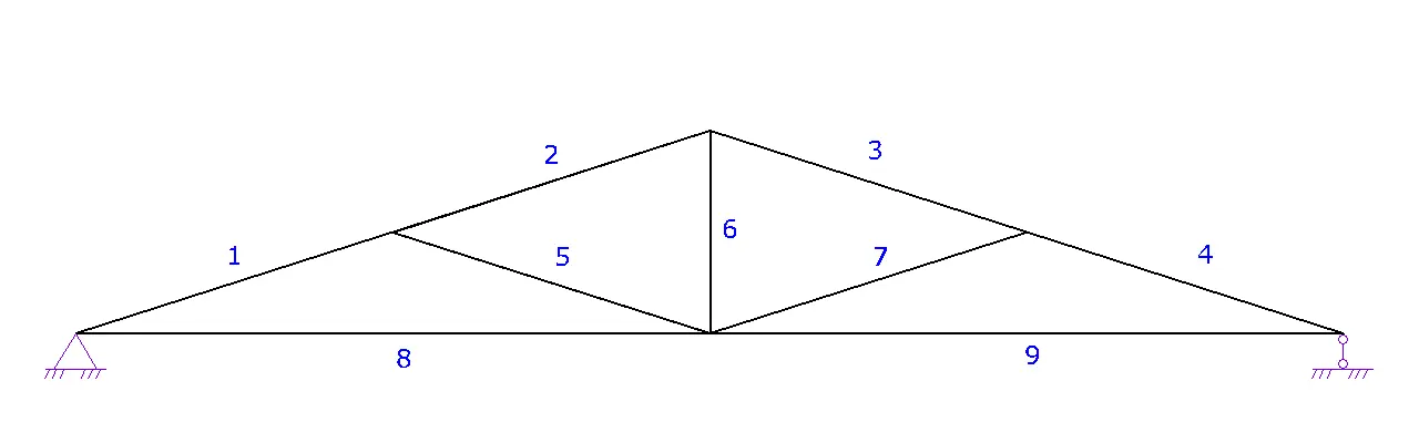
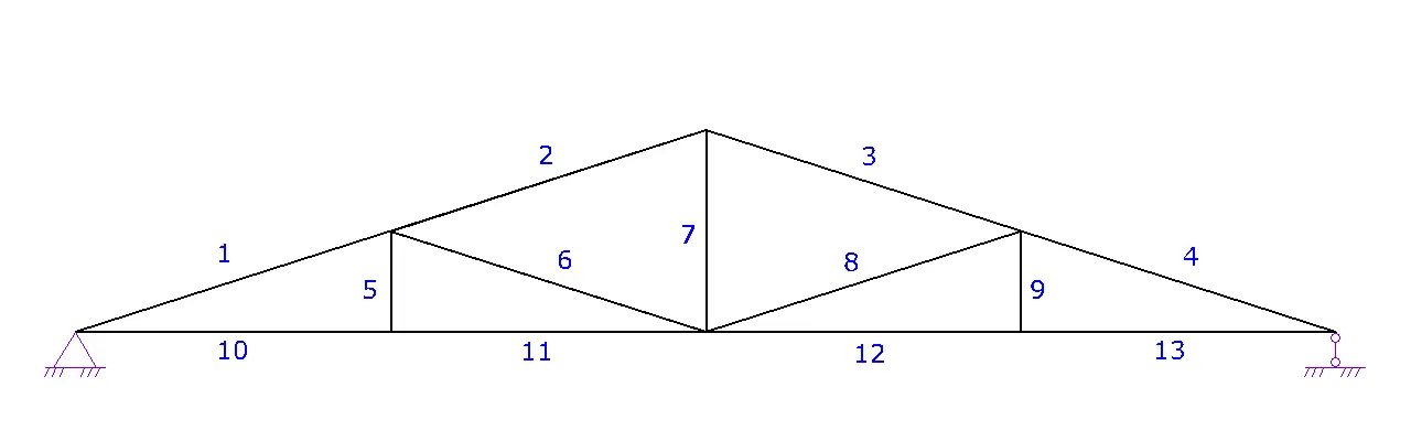
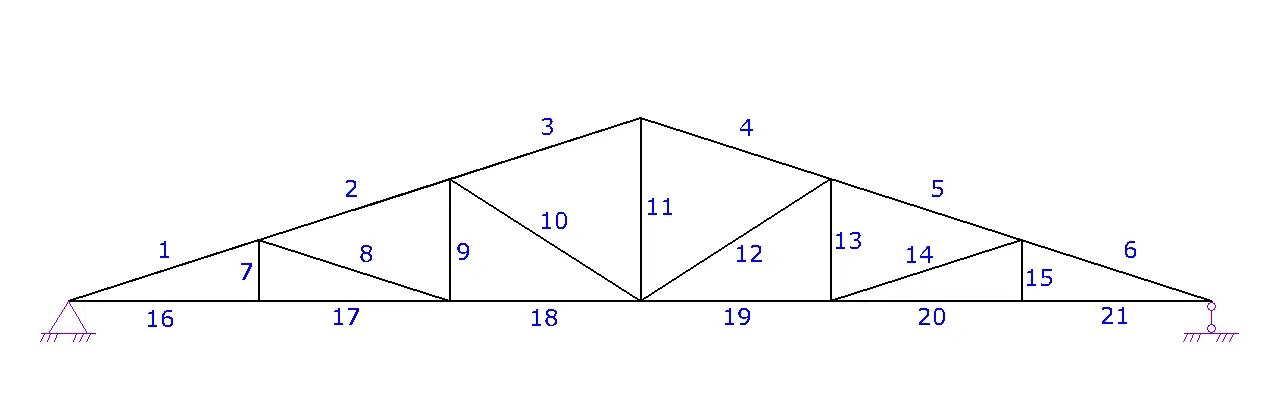
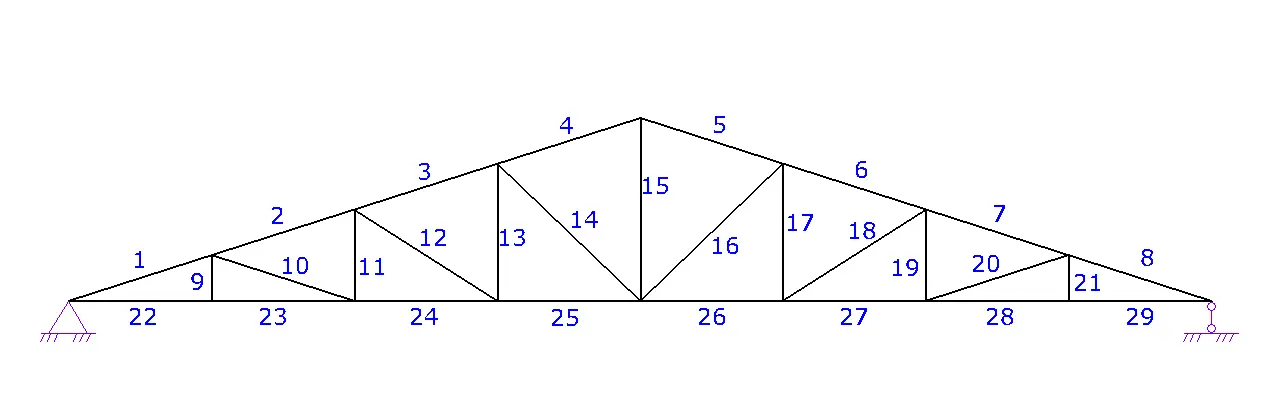
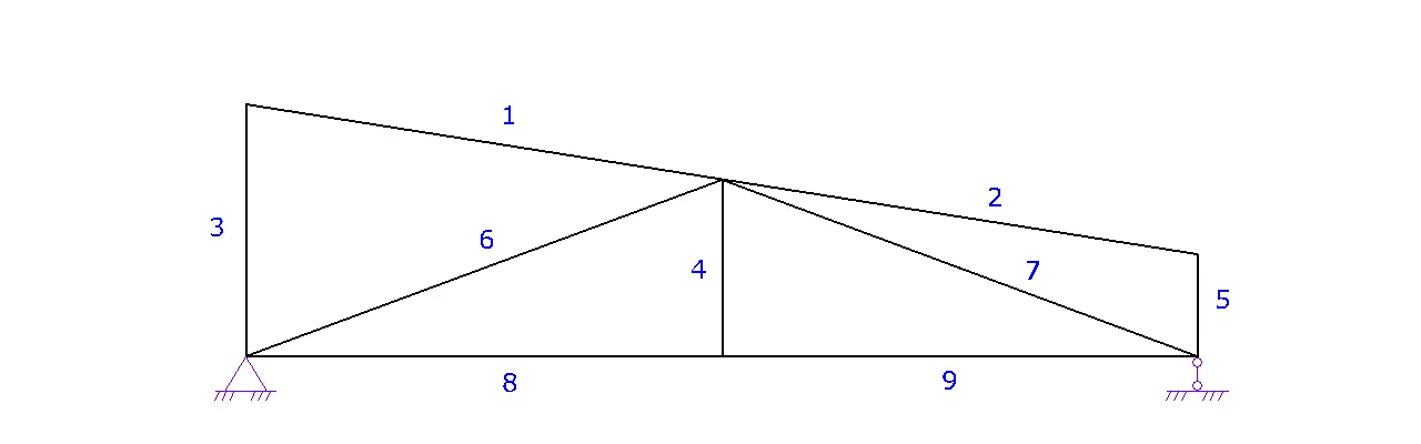
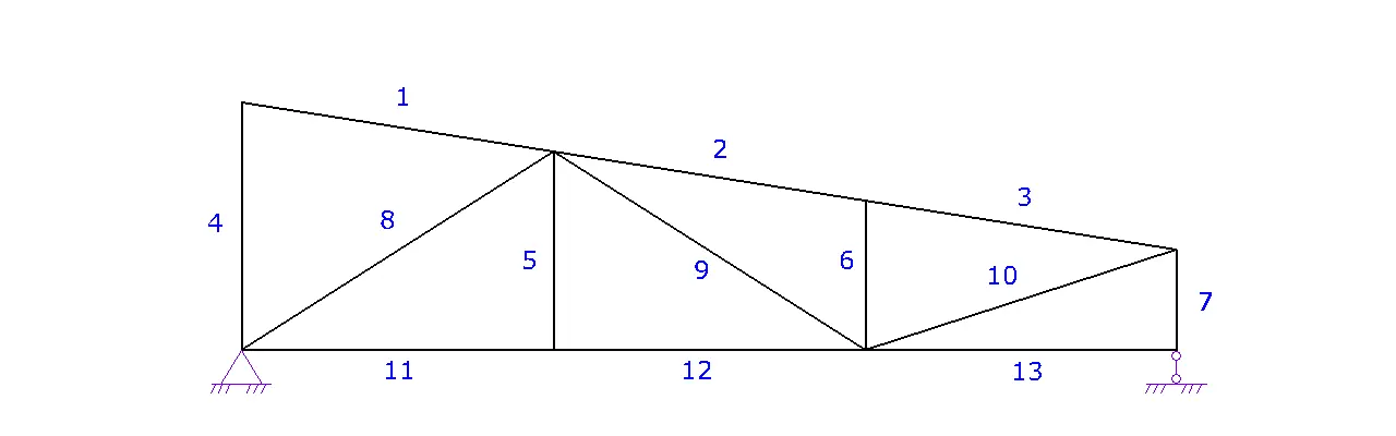
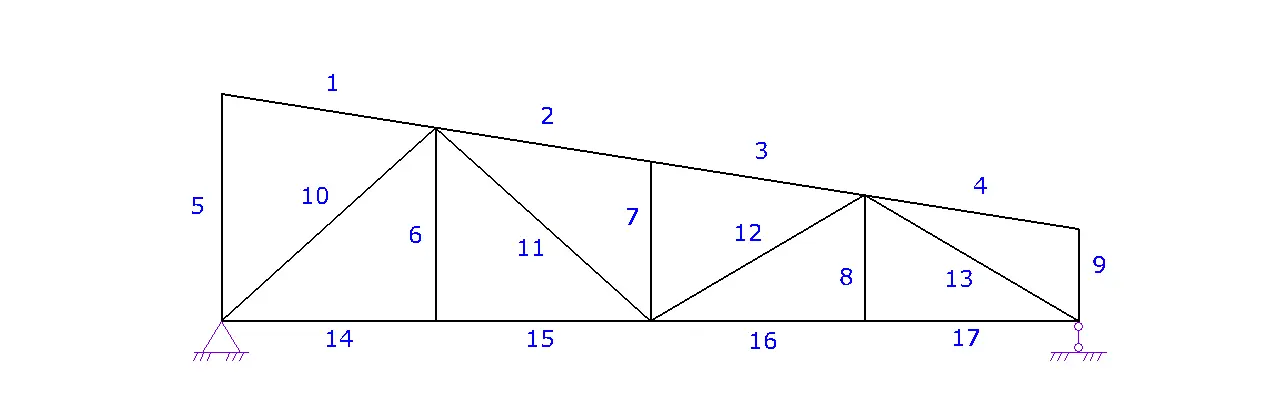
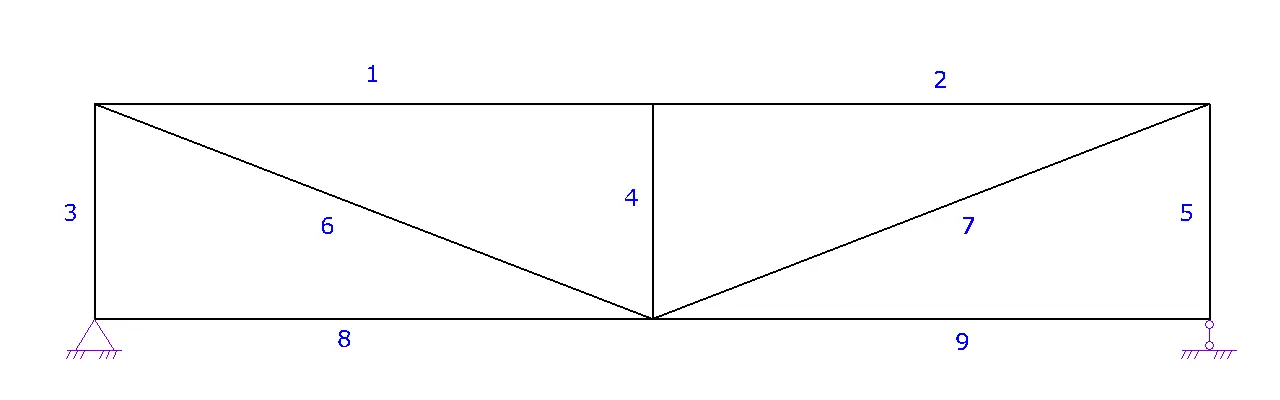
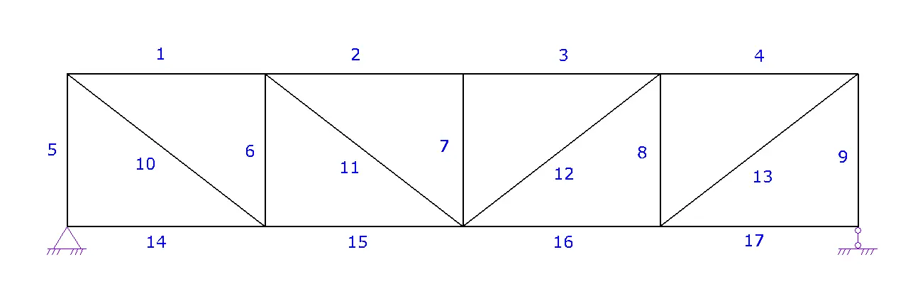
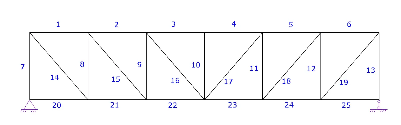
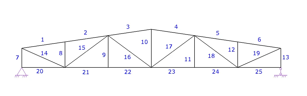
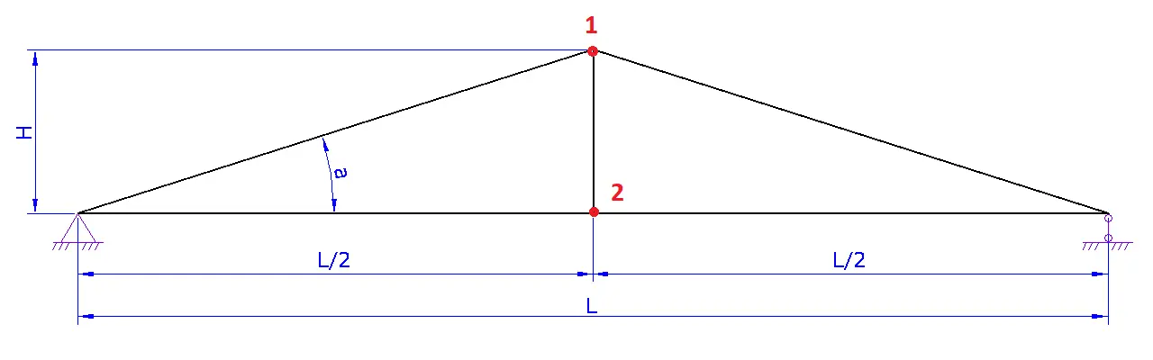
- Step 1. Truss Type. Select the required type of truss and proceed to the next step.
- Step 2. Truss Geometry.
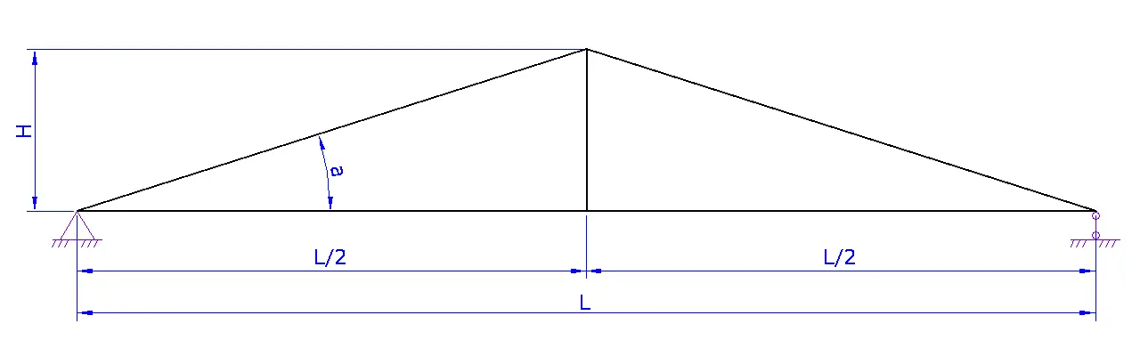
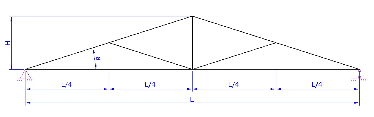
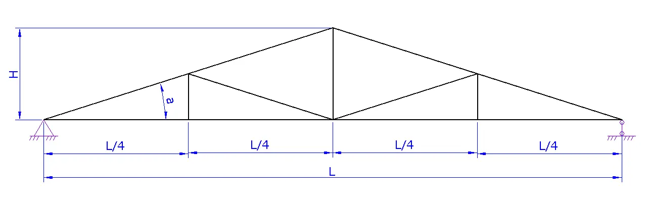
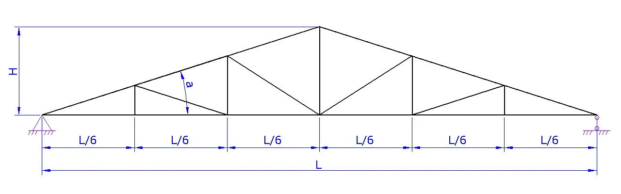
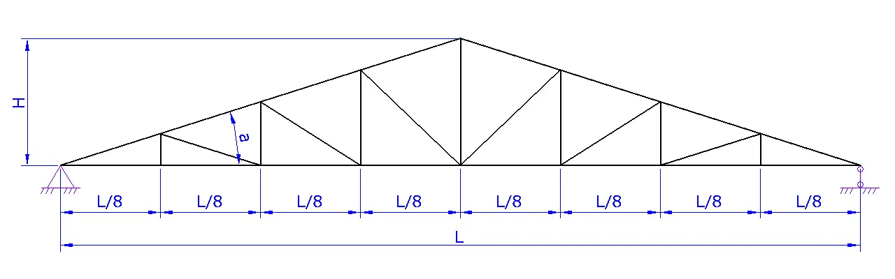
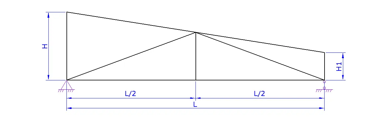
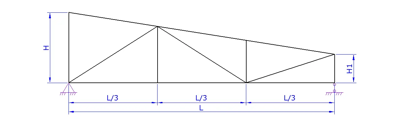
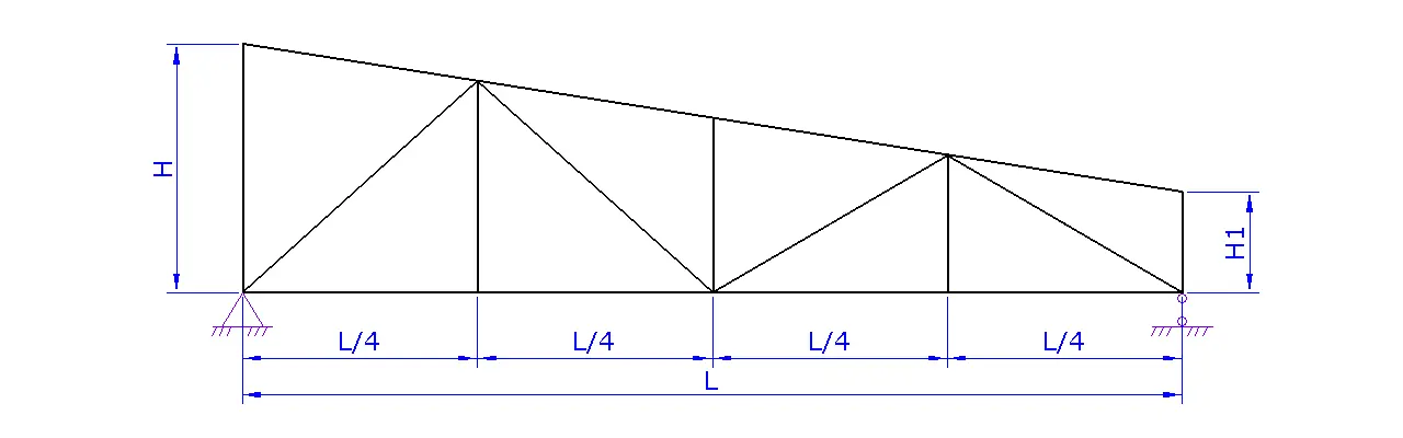
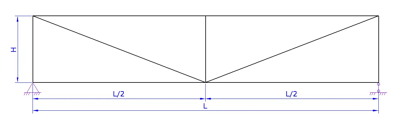
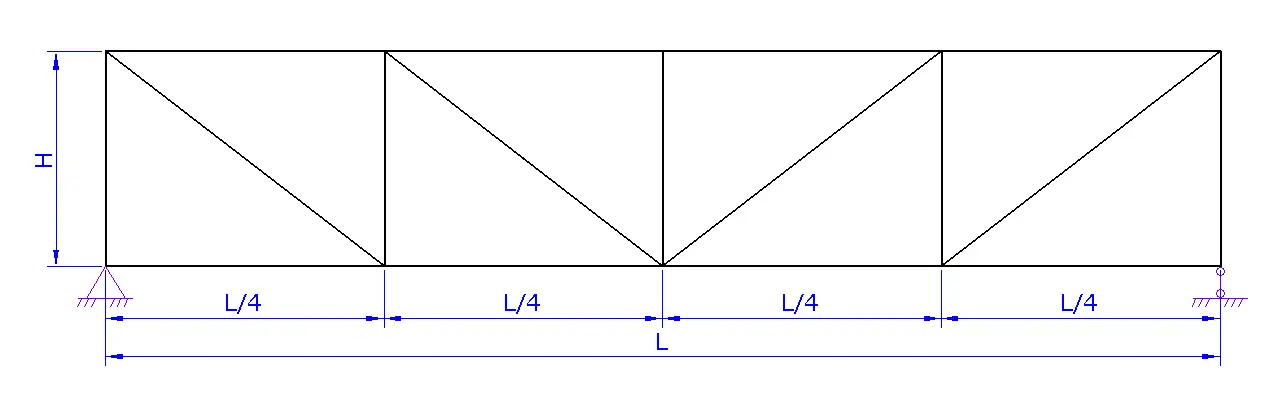
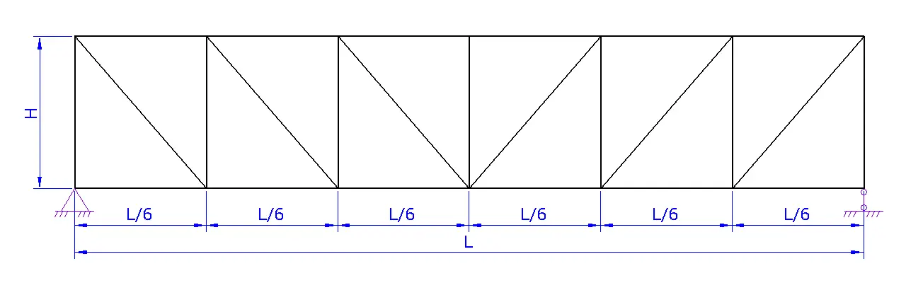
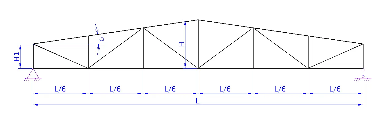
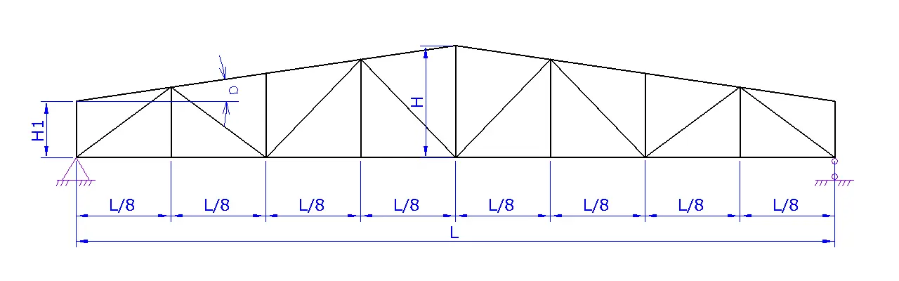
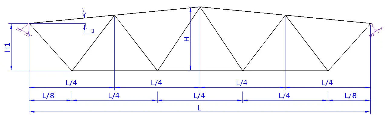
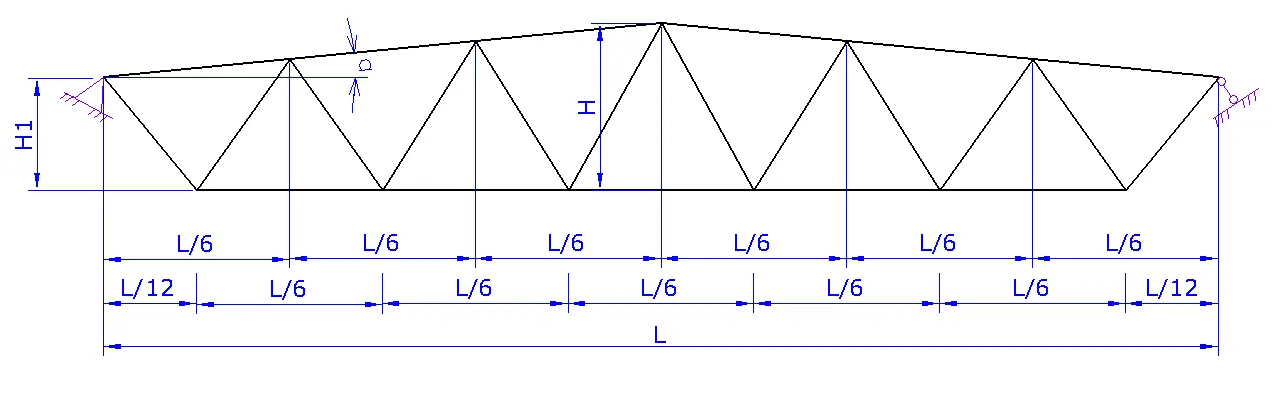
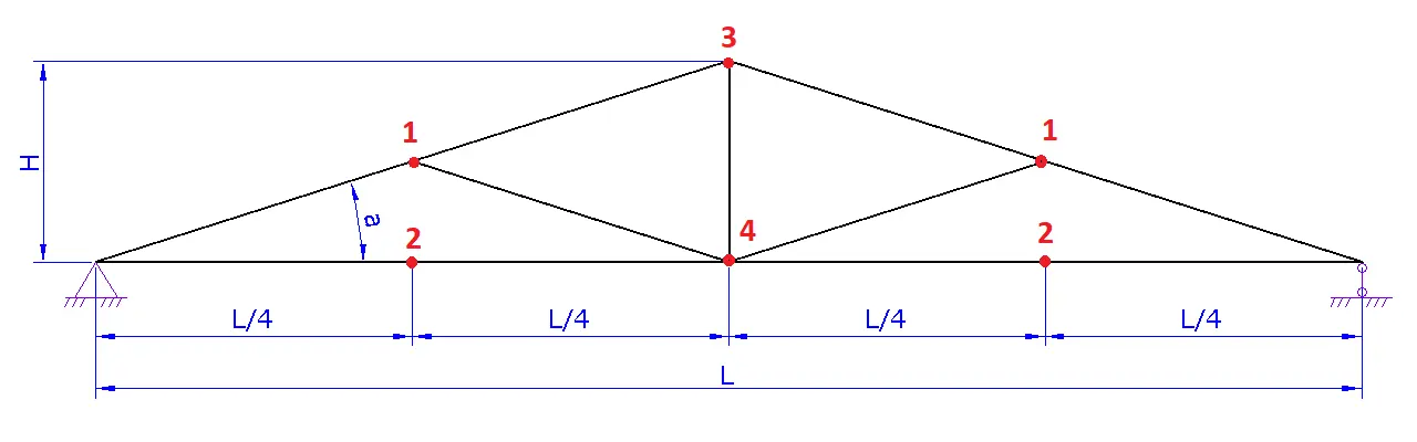
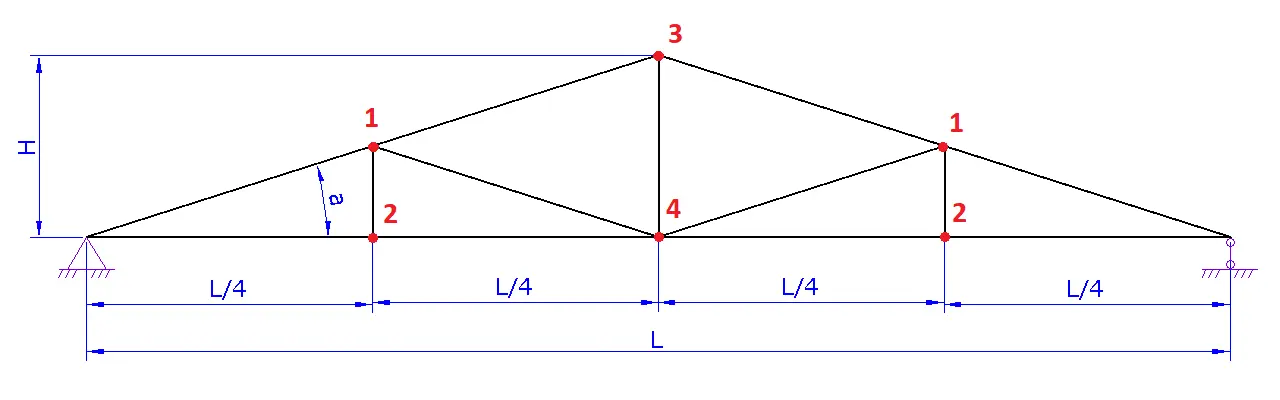
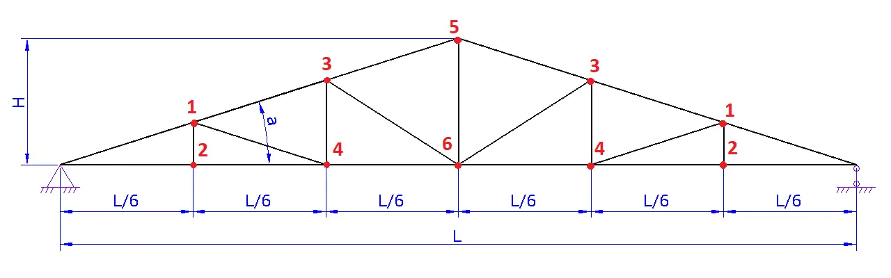
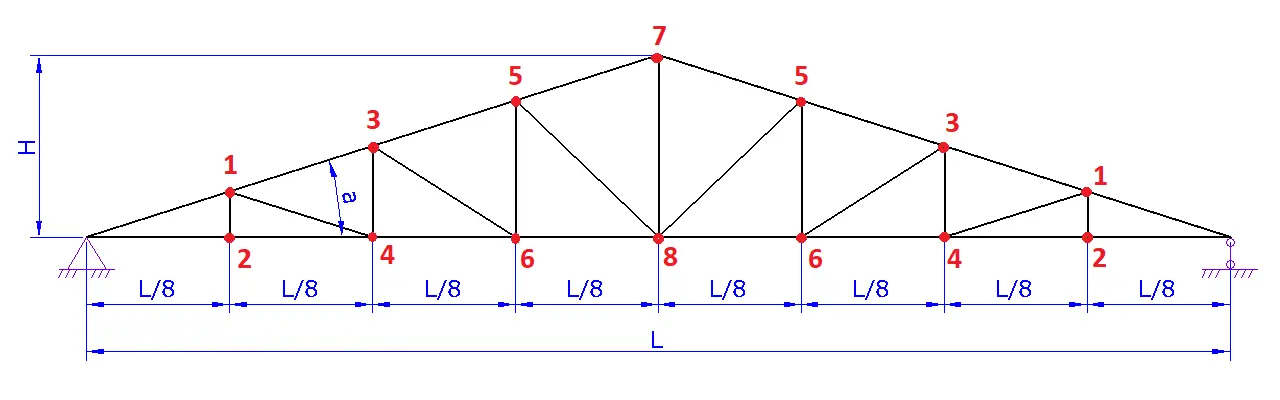
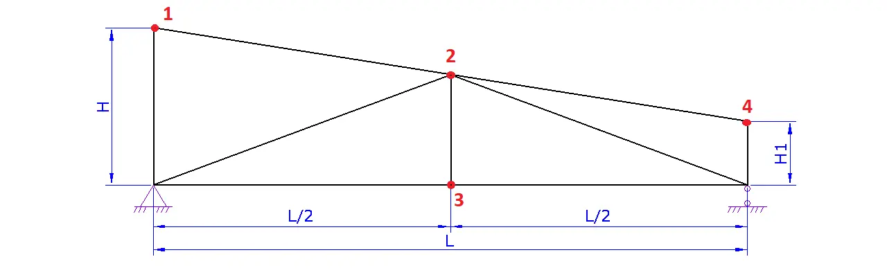
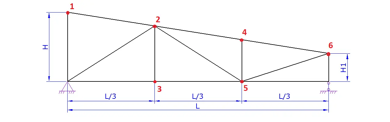
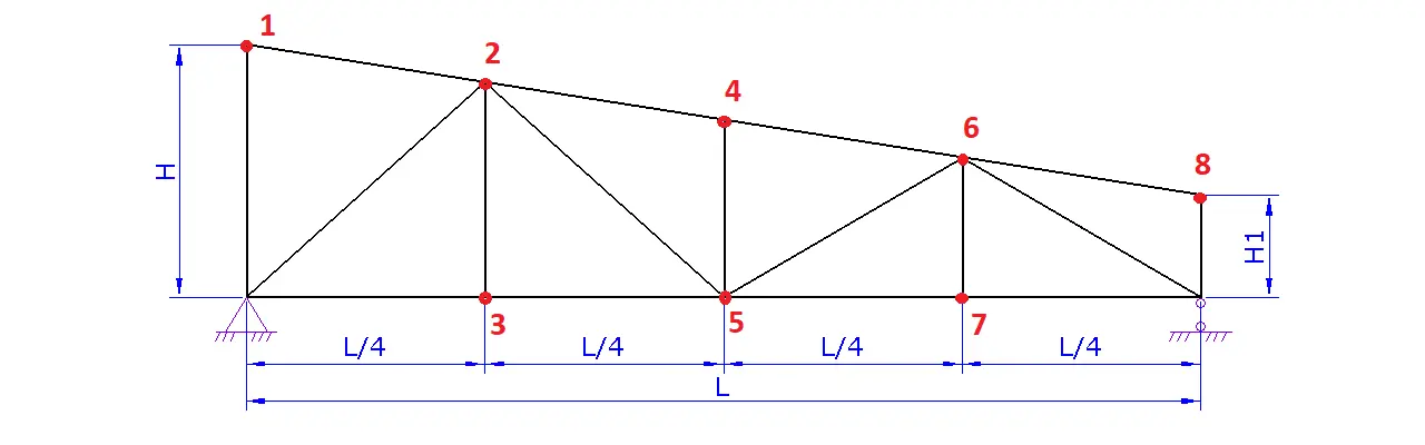
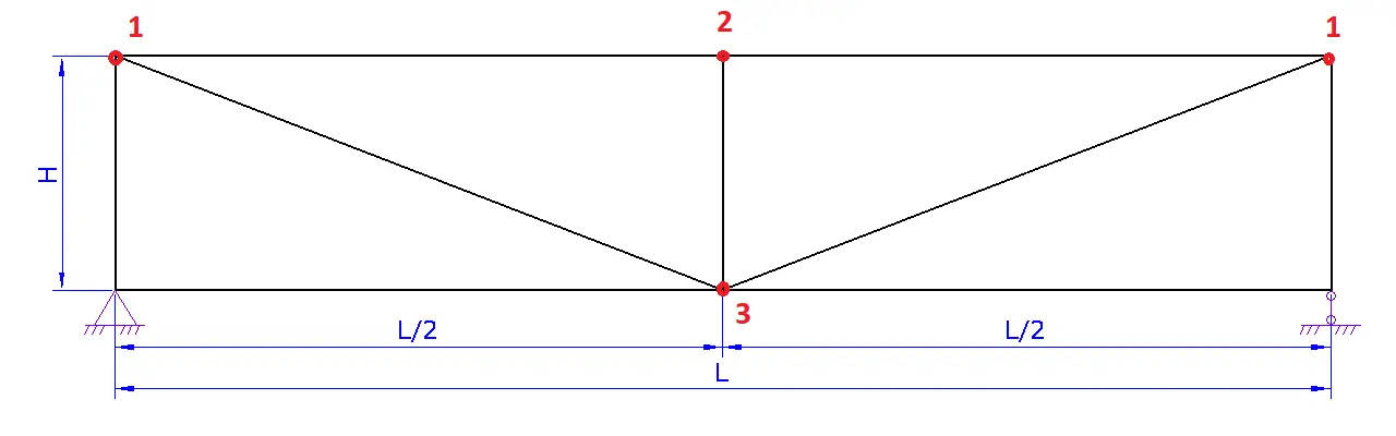
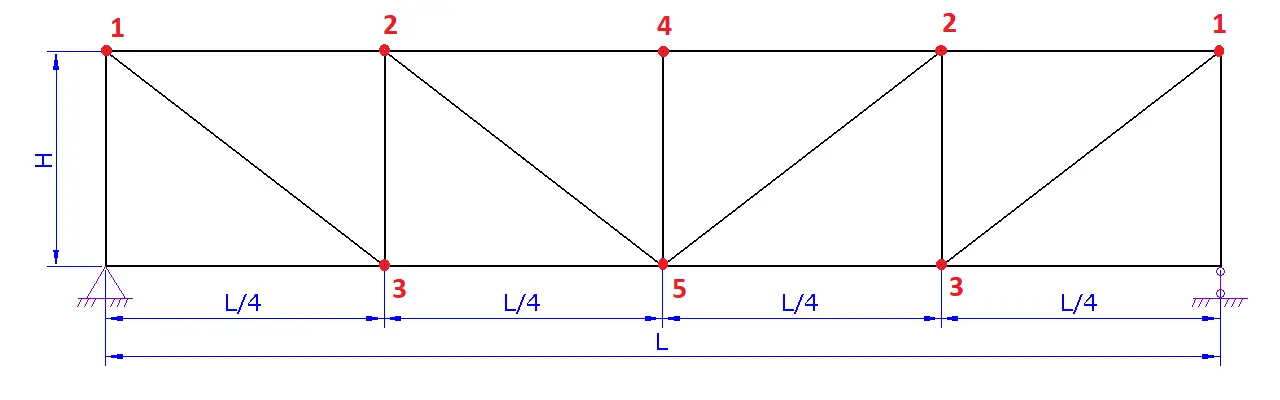
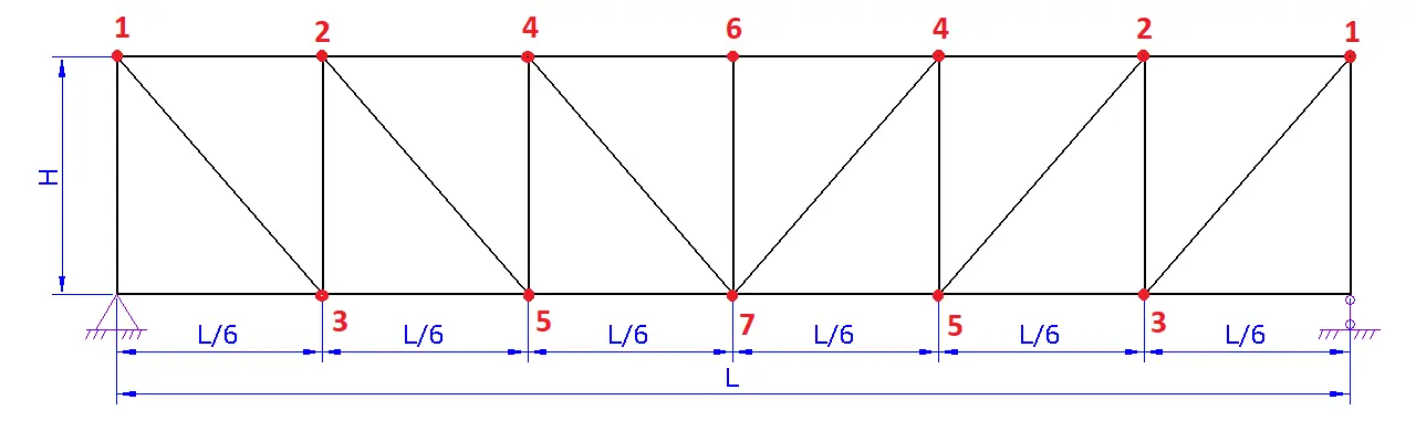
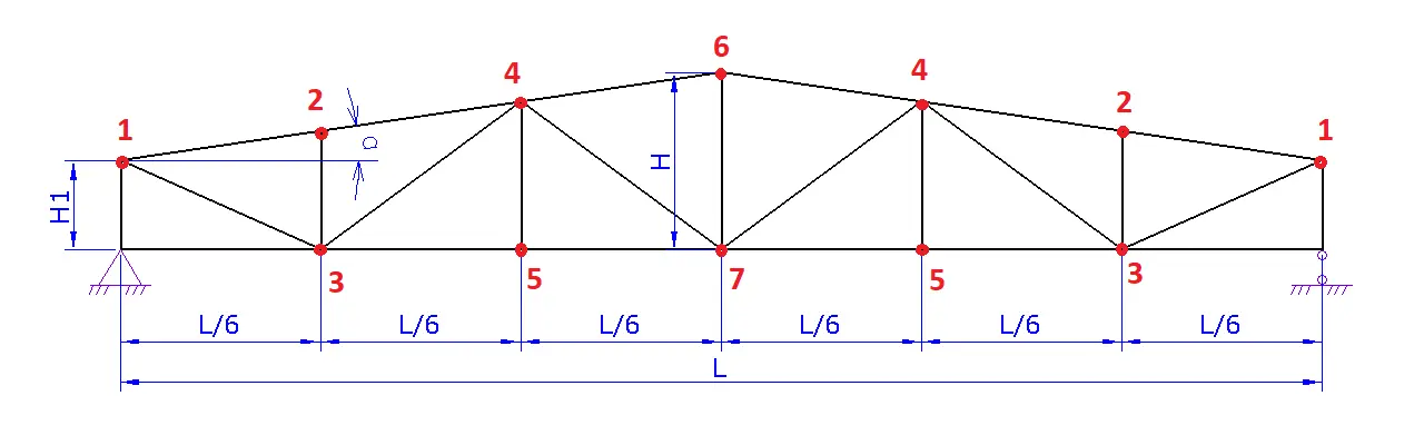
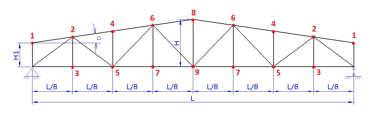
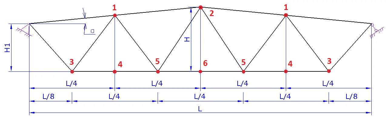
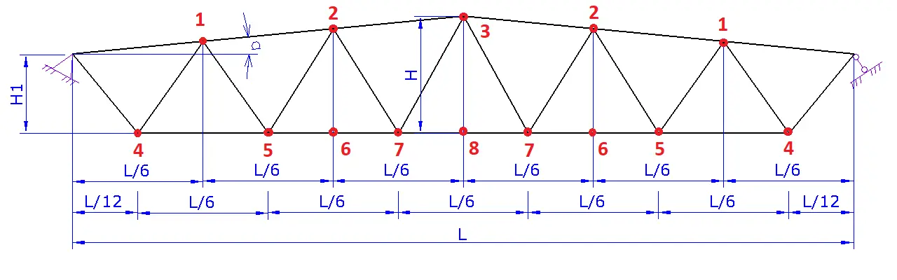
a. Specify the truss layout. At this stage, you can adjust the arrangement of the struts and braces for different truss lengths.
b. Enter the span of the truss L.
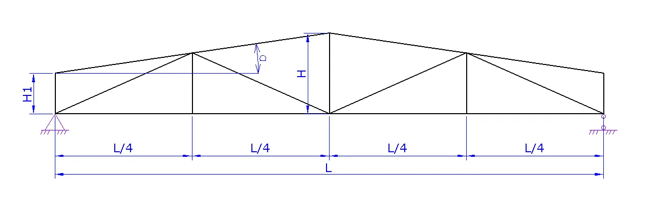
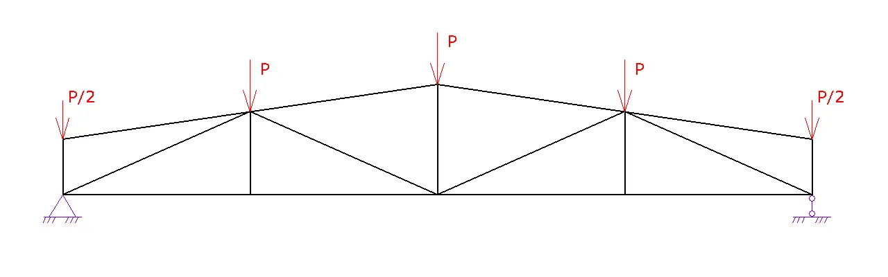
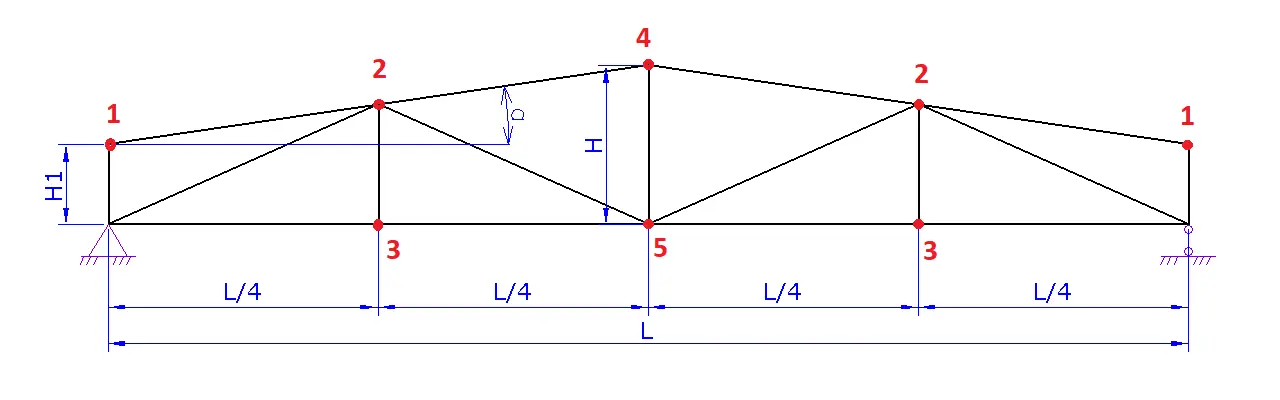
c. Specify the truss height H or the slope angle α.
d. If necessary, set the height of the truss at the support H1.
e. Proceed to the next step. - Step 3. Truss Loads. Enter the concentrated load applied to the truss joints or select the "Set load per area" option to input the distributed load per 1 m² along with the spacing between trusses. The concentrated load P at the joint will be automatically recalculated.
- Step 4. Truss Cross-Section and Material.
a. Choose the truss material: steel or wood.
b. Specify the cross-sections of the truss members and, if necessary, the grade or class of the material. You can press the "for all" button to apply the same cross-section to all members.
c. Proceed to the next step. - Step 5. Bracing. Based on the layout, position the bracing points of the truss joints out of plane. Bracing can be provided by connections between trusses or by purlins.
- Step 6. Calculation Results. Press the "Calculate" button to view the results.
The results will be presented in a table, where you can review the following data:
- Calculated forces in the truss members. A negative value indicates compression, a positive value indicates tension, and a zero value means the cross-section is considered adequate.
- Truss member cross-sections. Use the "-" and "+" buttons next to each cross-section to decrease or increase the size.
- Strength and stability reserve. A minimum strength reserve of 50% is required. If the reserve is highlighted in red and equals zero, you need to modify the truss layout or adjust the member cross-sections.
- Member flexibility. If a member’s flexibility is insufficient (highlighted in red or marked "NO"), that cross-section is not acceptable and the truss parameters must be revised.
- Approximate truss weight. Keep in mind that the cross-sections of the members should be standardized to achieve an optimal configuration.
Example:

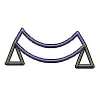
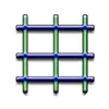
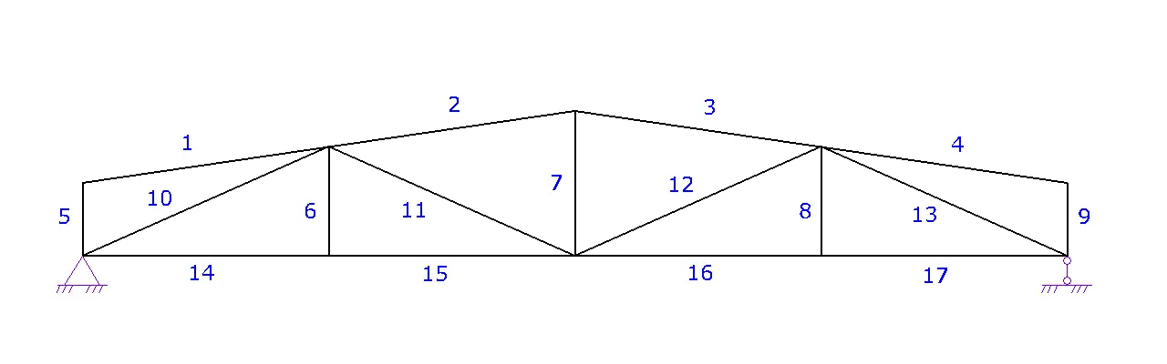
In the illustration, joints #1 and #3 are braced out of plane by purlins (blue), joint #2 is braced by horizontal connections on the bottom chord (brown), while joint #4 remains unbraced.
Additional Information:
- The density of wood is assumed to be 500 kg/m³.
- The density of steel is 7850 kg/m³.
- All truss joints are considered hinged.
- Truss supports: on the left – a fixed hinge, on the right – a sliding hinge.
- To ensure truss stability, connections between trusses must be established (this can be done in Step 5 "Bracing").
- For small spans, a beam can be used instead of a truss, after verifying its strength and deflection.
Latest Updates:
- Added verification for tensile and zero-force members based on flexibility.
- Introduced the ability to brace truss joints out of plane.
- Implemented the option to input distributed load per 1 m².
- Enabled setting bracing points with specific spacing.
In the illustration, nodes #1 and #3 are braced out of plane by purlins (blue), node #2 is braced by horizontal connections on the bottom chord (brown), while node #4 remains unbraced.
Additional Information:
- The density of wood is assumed to be 500 kg/m³.
- The density of steel is 7850 kg/m³.
- All truss joints are considered hinged.
- Truss supports: on the left – a fixed hinge, on the right – a sliding hinge.
- To ensure truss stability, connections between trusses must be established (this can be done in step 5 "Bracing").
- For small spans, a beam can be used instead of a truss, after checking its strength and deflection.
If you found this truss calculator useful, don’t forget to share it with your colleagues. We would also appreciate your feedback.
Latest updates:
- Added verification for tensile and zero members by flexibility.
- Added the ability to brace truss joints out of plane.
- Added the option to input distributed load per 1 m².
- Added the ability to set bracing points with a specific spacing.